


Asymmetric Half-Bridge Flyback Circuit Overview:
The Asymmetric Half-Bridge Flyback (AHB) is a soft-switching isolated power conversion topology. It combines the low stress of the half-bridge topology with the simplicity of the flyback, using transformer leakage/magnetizing inductance and a resonant capacitor to achieve ZVS for the primary-side switches, while recovering the leakage energy that is normally lost in a traditional flyback converter. It is therefore well suited to high-efficiency, high-power-density low-to-medium power applications (adapters, automotive power, server auxiliary supplies, etc.).
Detailed design of the 100~240W AC-DC AHB flyback circuit
Key Input/Output Specifications:
Input voltage: AC100V~AC240V
- Power factor
- 0.99
- Output power
- max 240W
- Output voltage
- this example 20-48V, regulation accuracy ±1%
- Output current
- this example 3-5A, current accuracy ±10%
- Power efficiency
- 94% @AC220V input, 20V 7A output
Overall Circuit Scheme
This design adopts an integrated "PFC + AHB asymmetric half-bridge" + synchronous rectification architecture. The front-end PFC stage uses the PFC-specific integrated chip DK8318 with built-in GaN FET switch, operating in highly efficient critical conduction mode (CrM) to achieve a power factor as high as 0.99. The main power conversion stage uses the DK8515 with dual integrated GaN FETs to implement the AHB (asymmetric half-bridge) topology, which achieves ZVS for the primary switches via resonance, effectively reducing switching losses. On the output side, the KP4060LGA high-performance synchronous rectifier controller replaces traditional Schottky rectifier diodes, minimizing secondary rectification loss and significantly boosting overall efficiency.
- Circuit Schematic
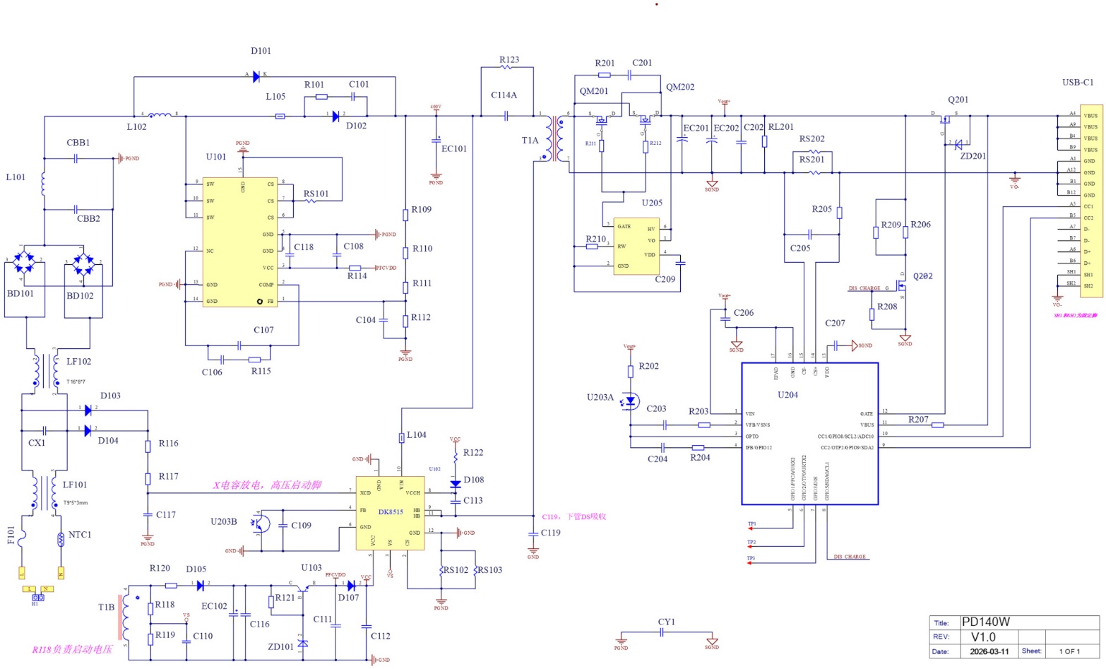
Key components BOM list:
| Component | Specification | Selection Rationale |
|---|---|---|
| Slow-blow fuse | T5A / 250V | Meets overcurrent protection for 240W max input current; compatible with 100V low-line input |
| Surge-limiting NTC | RT5D15 | Suppresses inrush current; meets IEC61000-4-5 Class 2 lightning surge requirement |
| Common-mode choke 1 | 15µH / 5A | Suppresses input common-mode EMI; meets CE EMC requirement |
| X2 capacitor | 104 / 275VAC | Filters input differential-mode interference |
| Common-mode choke 2 | 10mH / 5A | Second-stage common-mode suppression for extra EMC margin |
| Input AC rectifier bridge | 2 × 1kV / 5A | AC input rectification; voltage rating covers the 240V peak |
| Differential-mode suppression capacitor | 2 × 10⁵ / 450V (CBB) | Suppresses post-rectification differential-mode ripple |
| Differential-mode suppression choke | 80µH / 5A | Forms an LC filter with the differential-mode capacitor |
| PFC inductor | 150W: ATQ2516, 200µH 240W: ATQ2516, 130µH | Boundary conduction mode; see PFC Circuit Inductor Calculation |
| Built-in GaN PFC controller IC | DK8318 (700V / 16A, Rds(on)=0.1Ω, Coss=36.5pF) | Integrated GaN, CRM mode, high efficiency |
| PFC diode | 600V / 9A (fast recovery) | Low reverse-recovery loss, suited to high-frequency PFC |
| Input high-voltage E-CAP | 140W: 68µF / 450V 240W: 120µF / 450V | Sized at 0.4~0.5µF/W (DC400V) |
| Integrated GaN AHB power IC | DK8515 (600V / 11A, Rds(on)=0.16Ω) | AHB topology with ZVS support for higher efficiency |
| Main power transformer | 140W: ATQ2716, Lp=230µH 240W: PQ3225, Lp=150µH | Lp ≤ Vdc²·Dmax² / (8·Pin·fs) |
| Synchronous rectifier switch | CSLS165N15S2A (150A / 60A) | Low Rds(on) reduces rectification loss |
| Output filter capacitor | 560µF / 63V | Meets the 48V output voltage rating; reduces ripple |
| Feedback optocoupler | EL1018 (CTR ≥ 130%) | Isolated feedback stabilizes the output |
| Synchronous rectifier control IC | KP4060LGA | Drives the SR MOSFET for efficient rectification |
| PD protocol controller | HUSB368 (QFN-24L) | Supports PD3.1 EPR (48V/240W); built-in OVP/UVP/OCP/OTP protection |