


1Key input/output specifications of the 150~600W AC-DC design
Input voltage: AC100V~AC240V
- Output power
- 150-600W,
- Output voltage
- DC 10V~100V (specific voltage to be specified), regulation accuracy ±1%
- Output current
- 3A-30A, current accuracy ±5%
- Standby power
- below 1W (AC100V)
- Power efficiency
- 92% @AC100V, 95% @AC220V
2Overall circuit scheme of the 150~600W AC-DC design
This design uses the integrated "PFC + LLC resonant" controller TEA2017 together with a synchronous rectification scheme. The TEA2017 combined controller integrates front-end PFC control and half-bridge LLC control, with built-in drivers that directly drive GaN FETs and MOSFETs. The PFC stage can be configured as BCM boundary mode (below 300W) or CCM continuous mode (300W~600W). LLC resonant half-bridge control and drive are also integrated in the TEA2017; resonance achieves ZVS for the primary switches and ZCS for the secondary rectifiers. On the output side, the MP6924A high-performance synchronous rectifier (SR) controller replaces traditional Schottky rectifier diodes, minimizing secondary rectification loss and raising overall efficiency. The TEA2017 can directly drive GaN FET switches; using GaN significantly reduces high-frequency losses, allowing a smaller, more compact converter with less heat and higher efficiency.
3Circuit schematic of the 150~600W AC-DC design
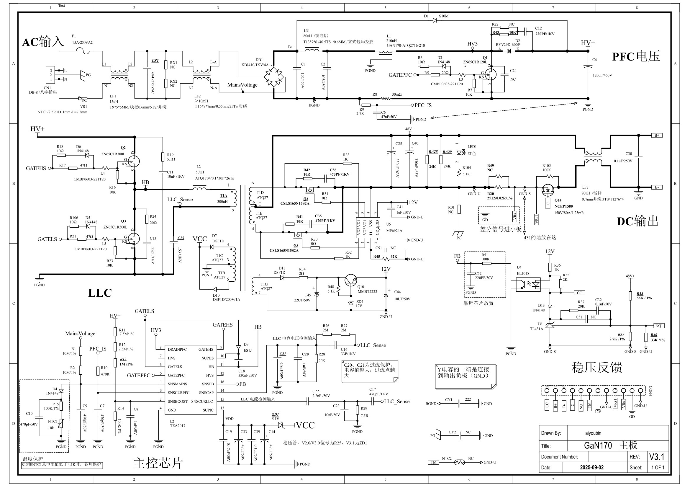
4Key components BOM calculation of the 150~600W AC-DC design
(This example is designed for 48V 4A; for other powers, currents and voltages, adjust the component parameter values)
| Component | Specification | Selection Rationale |
|---|---|---|
| Input fuse | T5A / 250V / plastic / slow-blow | Rated at 1.5~2× the maximum operating current; slow-blow type |
| Inrush current limiting | NTC / 2.5Ω / D11 | AC inrush generally limited below 60A; above 300W a relay bypass can be added |
| EMI common-mode choke 1 | 200W: 100µH (T9) 400W: 1.0mH (T16) 600W: 1.5mH (T20) | Adjust per EMC test results |
| EMI differential-mode capacitor (X2) | 200W: 0.47µF 400W: 1.0µF 600W: 2.2µF | Adjust per EMC test results; add X2 capacitors if necessary |
| EMI common-mode choke 2 | 200W: 15mH (T16) 400W: 10mH (T16) 600W: 10mH (T22) | Adjust per EMC test results |
| Input rectifier bridge | 200W: KBJ510 (1kV / 5A) 400W: KBJ1010 (1kV / 10A) 600W: KBJ1510 (1kV / 15A) | Allow margin for lightning surge and heat dissipation |
| EMI filter capacitor | 105 / 450V / CBB21 | Adjust per EMC test results |
| EMI differential-mode choke | 200W: 80µH (T13 Sendust) 400W: 50µH (T16 Sendust) 600W: 50µH (T22 Sendust) | Adjust per EMC test results |
| EMI filter capacitor (2nd stage) | 105 / 450V / CBB21 | Adjust per EMC test results |
| PFC bypass diode | S10M (1kV / 10A) | For PFC protection |
| PFC boost inductor | 200W: 220µH (PQ2625) 400W: 110µH (PQ3225) 600W: 550µH (KH130060A) | See PFC Boost Inductor Design & Current Calculation |
| PFC switch (GaN) | 200W: ZN65C1R120L 400W: ZN65C1R75T 600W: ZN65C1R35T | GaN FET, 650V, 120mΩ / 75mΩ / 35mΩ |
| PFC freewheeling diode | 200W: BYV29D-600P 400W: STTH12R06D 600W: STTH16R06D | Ultrafast recovery, 600V, 9A / 12A / 16A |
| PFC energy-storage capacitor | 200W: 100µF / 450V 400W: 200µF / 450V 600W: 300µF / 450V | Sized at 0.5µF/W |
| PFC overcurrent sense resistor | 200W: 50mΩ 400W: 30mΩ 600W: 20mΩ | I = Vcs / R (e.g. 0.3V / 0.05Ω = 6A ≥ Ipk) |
| LLC half-bridge switch | 200W: ZN65C1R300L 400W: ZN65C1R120L 600W: ZN65C1R090L | GaN FET, 650V, 300mΩ / 120mΩ / 75mΩ |
| LLC resonant inductor | 200W: 50µH (ATQ17) 400W: 45µH (PQ2620) 600W: 30µH (PQ2620) | See LLC Circuit Calculation |
| LLC power transformer | 200W: 300µH (ATQ27) 400W: 270µH (PQ3225) 600W: 180µH (PQ3230) | See LLC Circuit Calculation |
| LLC resonant capacitor | MMKP82 / 153 / 1kV | See LLC Circuit Calculation |
| PFC output voltage setting | 1206 / 7.5MΩ / 1% | Vout = (R11+R12+R13)/R14 + 1 × 2.5V |
| Synchronous rectifier MOSFET | 20V10A: 50V 10mΩ 50V8A: 130V 30mΩ 50V12A: 150V 20mΩ | Vds ≥ 2.5×Vout; Rds ≤ Vout/(200×Iout); tf≈65ns |
| DC output filter capacitor | 20V10A: 1000µF / 25V 50V8A: 100µF / 63V 50V12A: 150µF / 63V | Voltage rating ≥1.3×Vout; C ≥ 28×Pout/(f×Vout²), with margin |
| DC output voltage setting | 51kΩ / 1% | Vout = (R38/(R39+R40) + 1) × 2.5V ≈ 48V |
| Secondary SR IC | MP6924A | CTR ≥ 130% |
| Output protection switch | MOSFET, 150V / 80A | Controls output on/off |
| Output EMI common-mode suppression | — | Design per EMC test results |
Key power-device loss & thermal evaluation of the 150~600W AC-DC design
The main heat-generating components are the input rectifier bridge, the magnetic components of the PFC and LLC stages, power switches and power rectifiers. Heat dissipation differs with output power, voltage and current, but for well-designed products the thermal performance is roughly similar. The table below gives several concrete examples.
| Power | Symbol | 200W | 300W | 600W |
|---|---|---|---|---|
| Input rectifier bridge loss | P_ac_rect | 4.89W | 7.33W | 14.6W |
| PFC switch loss | P_pfc_mos | 2.10W | 4.86W | 5.90W |
| PFC inductor loss | P_pfc_ind | 3.90W | 4.20W | 5.20W |
| PFC diode loss | P_pfc_diode | 1.40W | 4.20W | 5.20W |
| LLC switch loss | P_llc_mos | 0.97W | 0.68W | 2.05W |
| LLC transformer loss | P_tran | 1.28W | 4.20W | 5.20W |
| LLC rectifier loss | P_llc_rect | 2.95W | 2.68W | 4.76W |
| LLC resonant inductor loss | P_llc_ls | 0.34W | 2.10W | 2.10W |
| Minimum power efficiency (@AC 90V) | Eff_total | 91.84% | 90.93% | 93.04% |