


1Key Input/Output Specifications
Input voltage: AC100V~AC240V
- Output power
- 601-2000W,
- Output voltage
- DC 10V~100V (specific voltage to be specified), regulation accuracy ±1%
- Output current
- 5A-50A, current accuracy ±5%
- Standby power
- below 1W (AC100V)
- Power efficiency
- 92% @AC100V, 95% @AC220V
2Overall Circuit Scheme
For AC-DC supplies or chargers in the 600~2000W range, the circuit mainly consists of five parts: an input EMI filter unit, a single-inductor CCM PFC power-factor-correction unit based on the NCP1654 control IC, a half-bridge LLC power conversion unit with the L6599 as core control IC, a CV/CC control unit based on an MCU and operational amplifiers, and an auxiliary power unit.
Within the 600W~2200W range the topology and circuit diagram are identical; only the selection of power semiconductors, power inductors, transformers and energy-storage capacitors differs. For the PFC and LLC power switches, prefer superjunction-process MOSFETs rated 600V or higher; for the output synchronous rectifier, ordinary low-voltage low-Rds(on) MOSFETs rated at more than 2× the output voltage suffice. The PFC inductor should use high-permeability Sendust or HIGH FLUX material; the transformer and resonant inductor should use N95 or similar ferrite.
See the key components BOM list below for details; the block diagram of each circuit unit is as follows:
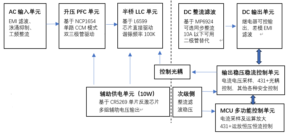
Figure 1: 600W~2000W main circuit block diagram
The auxiliary power supply is simple; for details refer to the "AI - Auxiliary Power Supply" document
3Main circuit schematic
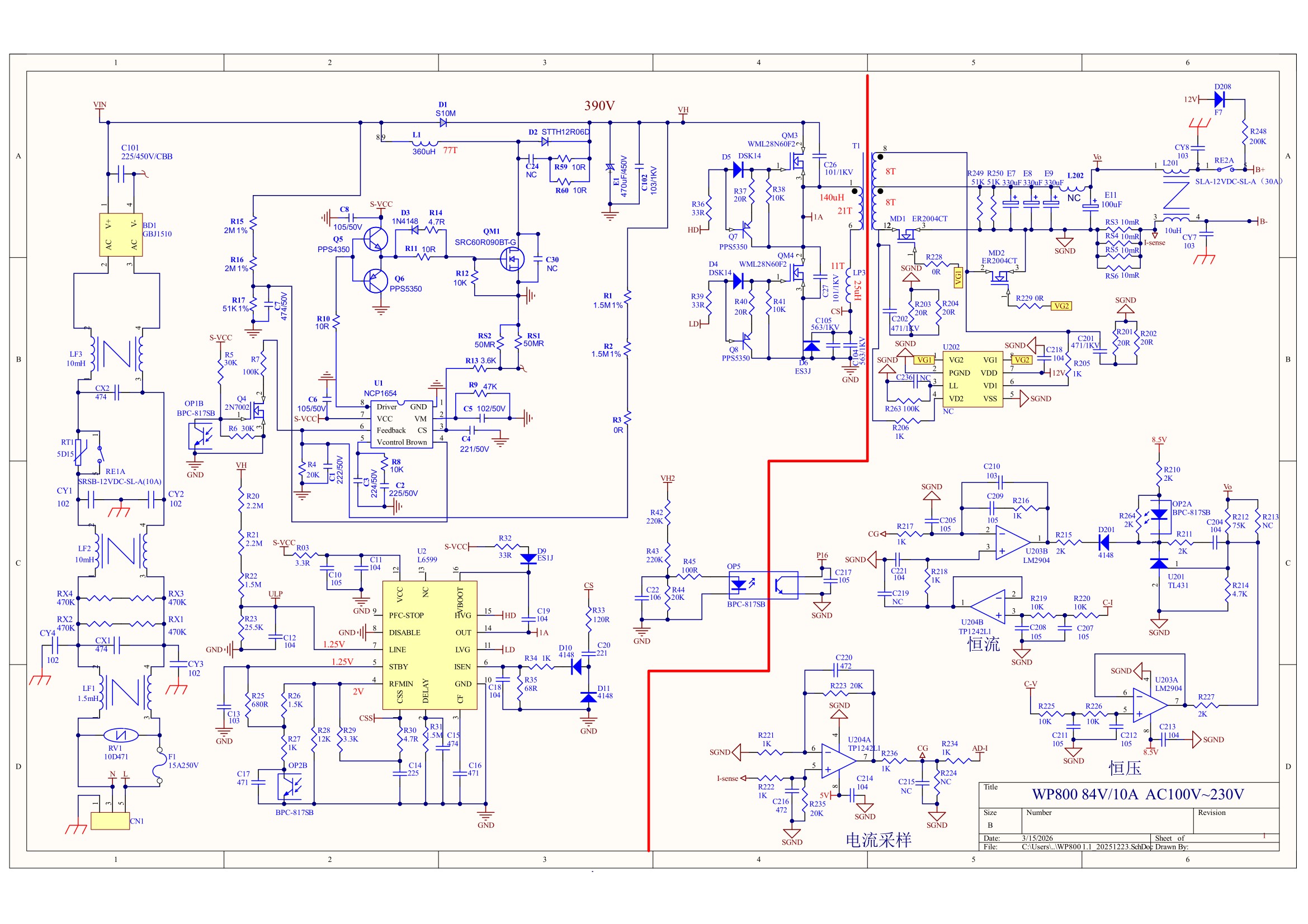
Figure 2: 600W~2000W main circuit schematic
4Key components BOM calculation of the main circuit (this example is designed for 58V 13A; for other output power/voltage/current refer to "LLC Circuit Calculation" for a detailed evaluation)
| Component | Specification | Selection Rationale |
|---|---|---|
| Input fuse | T15A / 250V / plastic / slow-blow | Rated at 1.5~2× the maximum operating current; slow-blow type |
| Inrush current limiting NTC | NTC / 5Ω / D11 | AC inrush generally limited below 60A |
| Input bypass relay | Contact current 10A~20A, coil supply 12V | Bypasses the NTC to reduce losses |
| EMI common-mode choke 1 | 1.5mH / 10A~20A | Adjust per EMC test results |
| EMI differential-mode capacitor (X2) | 0.47~2.2µF | Adjust per EMC test results |
| EMI common-mode choke 2 | 10mH / 10A~20A | Adjust per EMC test results |
| Input rectifier bridge | 800W: KBJ1510 (1kV / 15A) 1.2kW: GBJ2010 (1kV / 20A) 1.8kW: GBJ3010 (1kV / 30A) | Allow margin for lightning surge and heat dissipation |
| EMI filter capacitor | 225 / 450V / CBB21 | Adjust per EMC test results |
| PFC bypass diode | S10M (1kV / 10A) | For PFC protection |
| PFC boost inductor | 800W: 410µH (KH130060A) 1.2kW: 270µH (KH158060A) 1.8kW: 160µH (KH158060A) | See PFC Boost Inductor Design & Current Calculation |
| PFC switch | 800W: SRC60R090 1.2kW: OSG60R074 1.8kW: OSG60R074 | MOSFET, 600V / 90mΩ, 74mΩ |
| PFC freewheeling diode | STTH12R06D (600V / 16A, ultrafast recovery) | High-speed recovery for high-frequency PFC applications |
| PFC energy-storage capacitor | 800W: 330µF / 450V 1.2kW: 480µF / 450V 1.8kW: 600µF / 450V | Sized at 0.35~0.4µF/W |
| LLC half-bridge switch | 800W: WML28N60F 1.2kW: SRC60R090 1.8kW: IPW60R060 | MOSFET, 600V / 300mΩ, 90mΩ, 60mΩ |
| LLC resonant inductor | 800W: 25µH (PQ2620) 1.2kW: 15µH (PQ3220) 1.8kW: 11µH (PQ3220) | See LLC Circuit Calculation |
| LLC power transformer | 800W: PQ3530 1.2kW: PQ4040 1.8kW: PQ5040 | See LLC Circuit Calculation |
| LLC resonant capacitor | 800W: 563×2 / 1kV 1.2kW: 563×3 / 1kV 1.8kW: 563×4 / 1kV | See LLC Circuit Calculation |
| LLC output rectifier | 80V10A: 400V / 20A (ultrafast recovery) 50V25A: 150V / 10mΩ 50V35A: 150V / 7.5mΩ | Vds ≥ 2.5×Vout; Rds ≤ Vout/(200×Iout); tf≈65ns |
| DC output filter capacitor | 80V10A: 68µF / 100V 50V25A: 330µF / 63V 50V35A: 470µF / 63V | Voltage rating ≥1.3×Vout; C ≥ 28×Pout/(f×Vout²), with margin |
| Secondary SR IC | MP6924A | Commonly used for LLC synchronous rectification |
| Output relay | Current > 50A, coil supply 12V | Controls output on/off |
5Key Power-Device Loss & Thermal Evaluation
The main heat-generating components are the input rectifier bridge, the magnetic components of the PFC and LLC stages, power switches and power rectifiers. Heat dissipation differs with output power, voltage and current, but for well-designed products the thermal performance is roughly similar. The table below gives several concrete examples.
| Power | Symbol | 800W | 1200W | 1500W |
|---|---|---|---|---|
| Input rectifier bridge loss | P_ac_rect | 19.56W | 29.33W | 36.67W |
| PFC switch loss | P_pfc_mos | 14.0W | 16.0W | 23.0W |
| PFC inductor loss | P_pfc_ind | 19.0W | 25.0W | 32.0W |
| PFC diode loss | P_pfc_diode | 5.6W | 8.4W | 10.5W |
| LLC switch loss | P_llc_mos | 4.4W | 6.1W | 6.5W |
| LLC transformer loss | P_tran | 11.0W | 13.0W | 19.2W |
| LLC rectifier loss | P_llc_rect | 9.0W | 7.9W | 16.6W |
| LLC resonant inductor loss | P_llc_ls | 2.00W | 3.6W | 3.5W |
| Minimum power efficiency (@AC 90V) | Eff_total | 90.48% | 91.83% | 91.10% |