


1Detailed Circuit Design
Key Input/Output Specifications:
Input voltage: AC100V~AC240V,
- Maximum power
- 2000W @AC100V input, 3000W @AC220V input
- Output voltage
- DC 30V~DC90V (to be specified); this example 60V, regulation accuracy 1%
- Output current
- 25-80A; this example 50A, CC accuracy ±5%
- Full-load efficiency
- 92% @AC100V; 95% @AC220V
- Standby power
- approx. 2W (AC100V)
- Circuit Design Overview:
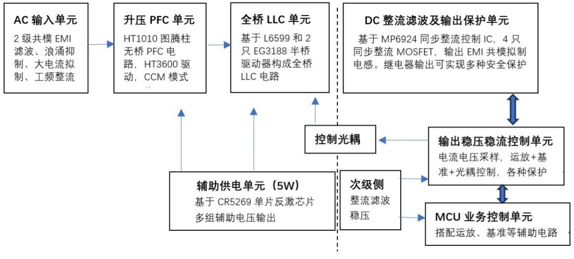
The main topology is a totem-pole bridgeless PFC circuit + full-bridge LLC circuit. The AC input EMI suppression consists of 2 common-mode chokes and 3 X capacitors, followed by a lightning surge absorber and an inrush limiter (NTC + relay), then the PFC boost inductor and totem-pole bridgeless PFC control circuit produce a 400V DC bus on the 450V 900µF energy-storage capacitor, feeding the full-bridge LLC that converts 400V to 60V; the LLC secondary uses synchronous rectification to raise efficiency and reduce losses. The output CV/CC circuit consists of 4 op-amps, a reference source and an optocoupler. A CR5269-based flyback chip provides auxiliary power for the whole circuit.
The PFC unit is based on the HT1010 digital chip for totem-pole bridgeless PFC control, paired with two HT3600 half-bridge driver ICs. The LLC unit extends the L6599 half-bridge LLC chip with two EG3188 half-bridge drivers to form the full-bridge LLC topology.
2Circuit Block Diagram
3Circuit Schematic (three partial diagrams)
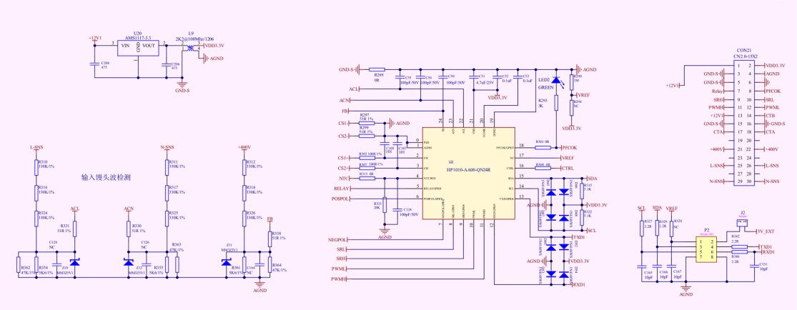
Figure 3-1: schematic of the PFC control circuit
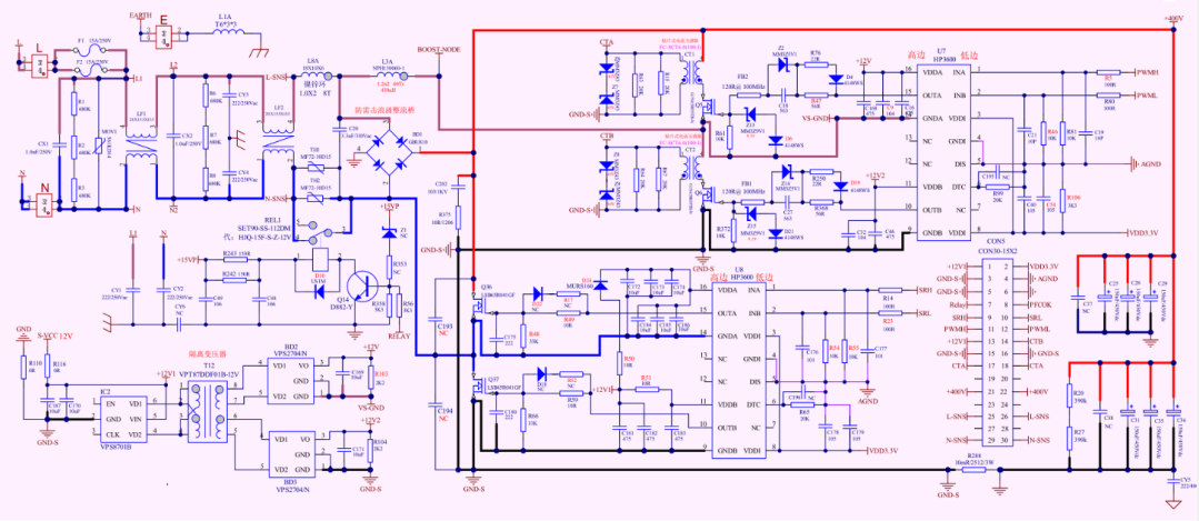
Figure 3-2: schematic of the AC input filter and PFC boost circuits
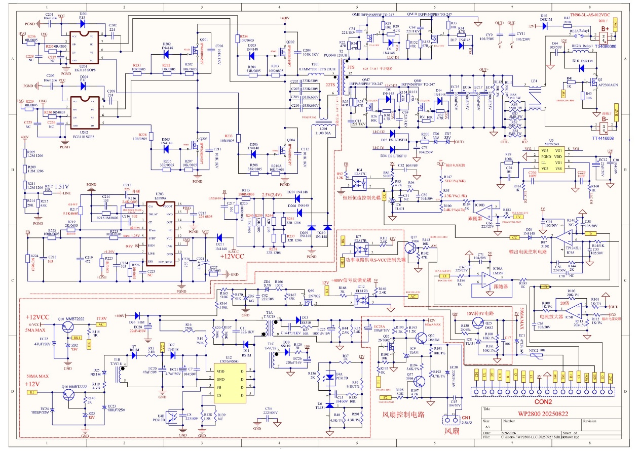
Figure 3-3: schematic of the full-bridge LLC converter and auxiliary power unit
4Key components BOM (example 56V 50A output; when output voltage or power differs, recalculate the parameters of components shown in red)
| Component/Function | Specification | Calculation Method & Notes |
|---|---|---|
| Input fuse | T15A / 250V / slow-blow | ≥ 1.5× the AC maximum operating current; slow-blow type |
| Lightning surge varistor | 561KD14 | Withstands 2kV 1kA repeated or 4kV 2kA single lightning strikes |
| NTC inrush limiter | MF72-10D15 | Suppresses power-on inrush |
| Bypass relay | Rated DC100V / 30A | Bypasses the NTC to reduce operating losses |
| EMI common-mode choke 1 | 2mH / 25A | Adjust per EMI test results |
| EMI common-mode choke 2 | 1mH / 25A | Adjust per EMI test results |
| X2 differential-mode capacitor 1 | 1µF / 275V | EMI suppression |
| X2 differential-mode capacitor 2 | 2.2µF / 275V | Adjust per EMI test results |
| Surge-protected rectifier bridge | 800V / 10A | Surge-protection bypass for the totem-pole bridgeless PFC |
| Input E-CAP | 6 × 150µF / 400V | ≥ 0.3µF/W (see SMPS Energy-Storage Capacitor Calculation) |
| PFC inductor | 165µH / 35A | See PFC Boost Inductor Design & Current Calculation |
| PFC high-speed switch | G1N65R035TB-N (650V / 35mΩ) | Low conduction loss, high-speed switching |
| PFC low-speed switch | LSB65R041GF (650V / 36mΩ, tr=26ns, tf=6.8ns) | Works with the high-speed switch for high efficiency |
| PFC control IC | HT1010 | PFC control |
| PFC driver IC | HT3600 | PFC drive |
| PFC current transformer | 30A, 1:100 (SMD) | Current sensing |
| Half-bridge driver IC | EG3118 | LLC drive |
| LLC control IC | L6599A | LLC control |
| LLC full-bridge switch | IPW60R045P7 (650V / 45mΩ, Coss=190pF, tr=15ns, tf=4ns) | Main power switch |
| LLC transformer | PQ5040 | See LLC Circuit Calculation |
| LLC resonant inductor | PQ3225, 25µH / 15A | See LLC Circuit Calculation |
| LLC current transformer | 30A, 1:100 | Current sensing |
| LLC resonant capacitor | 4 × 333 / 630V | See LLC Circuit Calculation |
| Synchronous rectifier IC | MP6924A | Synchronous rectification control |
| Synchronous rectifier MOS | IRFP4568PBF (150V / 4.8mΩ, 58V / 50A output) | Vds ≥ 2×Vout; Rds ≤ 0.1/Iout; parallel operation supported; Coss=977pF |
| Output E-CAP | 63V / 250µF | C ≥ 14×Pout/(f×Vout²); see energy-storage capacitor calculation |
| Output relay | DC100V / 80A | Controls the output |
| Output current sampling | 1.25mΩ | Rds ≤ 0.05/Iout; for wide-range high accuracy use a Hall sensor |
| Output common-mode filter | 10µH / 50A | Adjust per EMI test results |
5Key Power-Device Loss & Thermal Evaluation
The main heat-generating components are the input filter, the magnetic components of the PFC and LLC converters, power switches and power rectifiers. Below is the heat estimation method based on this example (input AC100V, output 56V 35A); for other output voltages and powers, adjust the parameters and recalculate:
The four bridge arms of the LLC converter have essentially identical losses; per arm:
Total loss of items 1~10 above is 176W, so the overall efficiency is: 2000/(2000+176)=91.9%