Known Parameters
Determine the DC input voltage (PFC voltage)
Vin_min = 380 V
Vin_nom = 390 V
Vin_max = 400 V
Output Voltage and Power
Vout_min = 20 V
Vout_max = 48 V
Pout = 140 W
Iout = Pout / Vout_max = 2.917 A
Operating Frequency and Efficiency
fs_min = 150 kHz
η = 96%
Pin = Pout / η = 150 W
Other Parameters
Take the maximum duty cycle (energy-storage switch / lower switch duty cycle): Dmax = 0.47
Calculate the Turns Ratio nmax = Vor / Vout_max + Vd = 3.7
Secondary MOSFET Stress
Vsec_d = Vin_max / n = 108.108 V
Peak Current
Ipk_nom = 2 ⋅ Pin / (0.9 ⋅ Vor) = 1.777 A
Overcurrent Multiplier
OCP_Rate = 1.2
Peak Current at the Overcurrent Multiplier
Ipk_max = 2 ⋅ Pin ⋅ OCP_Rate / (0.9 ⋅ Vor) = 2.132 A
Inductance
Lp = Dmax ⋅ (Vin_nom − Vor) / (fs_min ⋅ Ipk_max) = 276.551 μH
Designed Inductance
Lp_real = 280 μH
Transformer Core Selection
Input power (W): Pin = Pout / η = 150 W; window utilization factor: Ku = 0.2; waveform factor: Kf = 1; operating frequency (Hz): f = 150000 Hz; maximum operating flux density (T): Bmax = 0.2 T; current density (A/cm²): J = 600 A/cm²
AP value calculation:
AP = Pin ∙ 10⁴ / (Ku ⋅ Kf ⋅ f ⋅ Bmax ∙ J) = 0.417 cm⁴
Actually selected core: ATQ2716, with core parameters:
Ae = 129 mm²
Aw = 60 mm²
Actual AP value: Ap_real = Ae ⋅ Aw = 0.774 cm⁴ (the selected core AP is larger than the calculated AP)
Calculate the Turns Ae value: Ae = 129 mm²; maximum flux density: Bmax = 0.2 T
Primary turns: Np = Ipk_nom ⋅ Lp_real / (Ae ⋅ Bmax) = 19.693
Secondary turns: Ns = Np / n = 5.322
Actual secondary turns: Ns_real = 6
Primary turns: Np1 = Ns_real ⋅ n = 22.2
Actual primary turns: Np_real = 22
Actual turns ratio: nreal = Np_real / Ns_real = 3.667
Transformer leakage inductance (typically 2%-3%): Lktemp = Lp_real ⋅ 3% = 8.4 μH
Estimated transformer leakage inductance: Lk = 8.4 μH
Estimated resonant capacitance: Cr = 1 / (π² ⋅ Lk ⋅ (0.9 − Dmax) ⋅ fs_min²) = 99.123 nF
Triangular wave RMS (energy storage period): Irms_tri = nreal ⋅ Vout_max ⋅ (1−Dmax) / (Lp_real ⋅ fs_min ⋅ Dmax / 3) = 0.879 A
Sine wave RMS (resonance period RMS): Irms_sin = ... (complex formula, original value) = 0.76 A
Primary RMS current: Ip_rms = √(Irms_tri² + Irms_sin²) = 1.162 A
Secondary RMS current: Isec = Ip_rms ⋅ (1−Dmax) / Dmax = 4.566 A
Primary RMS current: Irms = Ip_rms
Primary current density: Jp = 6 A/mm²; required wire cross-section: Sp = Irms / Jp = 0.194 mm²; selected single-strand diameter: ϕp = 0.1 mm; minimum strand count: Xp = Sp / (π ⋅ ϕp² / 4) = 24.66; actual strand count: Xp_real = 30
Secondary current density: Js = 6 A/mm²; required wire cross-section: Ss = Isec / Js = 0.761 mm²; selected single-strand diameter: ϕs = 0.1 mm; required strand count: Xs = Ss / (π ⋅ ϕs² / 4) = 96.891; actual strand count: Xs_real = 150
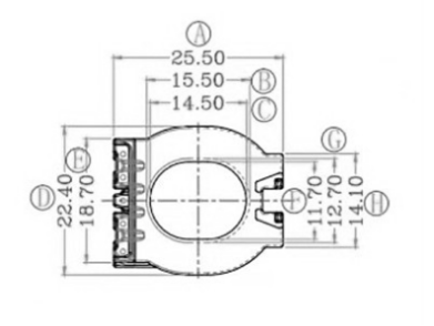
FIG.01 · CLICK TO ENLARGE The above is the ATQ2716 bobbin data; mean turn length = 25.5 + 15.5 / 2 ⋅ π = 0.064 m. Take the mean length per turn (MLT): MLT = 0.064 m
Primary Copper Loss
Total winding length: Ltotal = Np_real × MLT = 22 × 0.064 = 1.175 m; single-strand cross-section: Asingle = π ⋅ (0.1×10⁻³)² = 7.854×10⁻⁹ m²; total cross-section of 30 parallel strands: Atotal = 30 × Asingle = 2.356×10⁻⁷ m² (copper resistivity ρ ≈ 2.3×10⁻⁸ Ω·m at 100°C); DC resistance: Rdc = ρ ⋅ Ltotal / Atotal = 0.279 Ω; AC/DC resistance ratio: Fr = 1.2; primary RMS current: Irms = 1.162 A; copper loss: Pcu = Irms² × Rdc × Fr = 0.183 W
Secondary Copper Loss
Total winding length: Ltotal = Ns_real × MLT = 6 × 0.064 = 0.32 m; single-strand cross-section: Asingle = 7.854×10⁻⁹ m²; actual parallel strands counted as 150 (differs slightly from the original text); total cross-section: Atotal = 150 × Asingle; DC resistance: Rdc = 0.019 Ω; AC/DC resistance ratio: Fr = 1.2; secondary RMS current: Irms = 4.566 A; copper loss: Pcu = Irms² × Rdc × Fr = 0.154 W
Core Loss
Pcore = K ⋅ f^a ⋅ B^b ⋅ Ve
fs is frequency, B is the flux density change, Ve is the effective core volume; fs in kHz, Bac in mT, Ve in cm³, Pcore in mW
For this case:
B = 200 mT
Core volume Ve = 6.145 cm³
Switching frequency fs = 150 kHz
Pcore = 1×10⁻⁶ ⋅ 150^1.25 ⋅ 200^2.55 ⋅ 6.145 ≈ 2.378 W
Total Transformer Loss
Transformer loss = 0.183 W + 0.154 W + 2.378 W ≈ 2.715 W