


Circuit function: AC100~240V powered, multiple outputs (primary 20V, secondary 12V, isolated 12V), 10W
Circuit description: the auxiliary power unit uses a flyback topology with the JW1520 or CR5269 as main controller. See "AI - Flyback AC-DC Power Supply Design" for details. The secondary side provides two independent outputs, 12V and isolated 12V; the primary side provides 20V mainly to power the PFC and LLC chips.
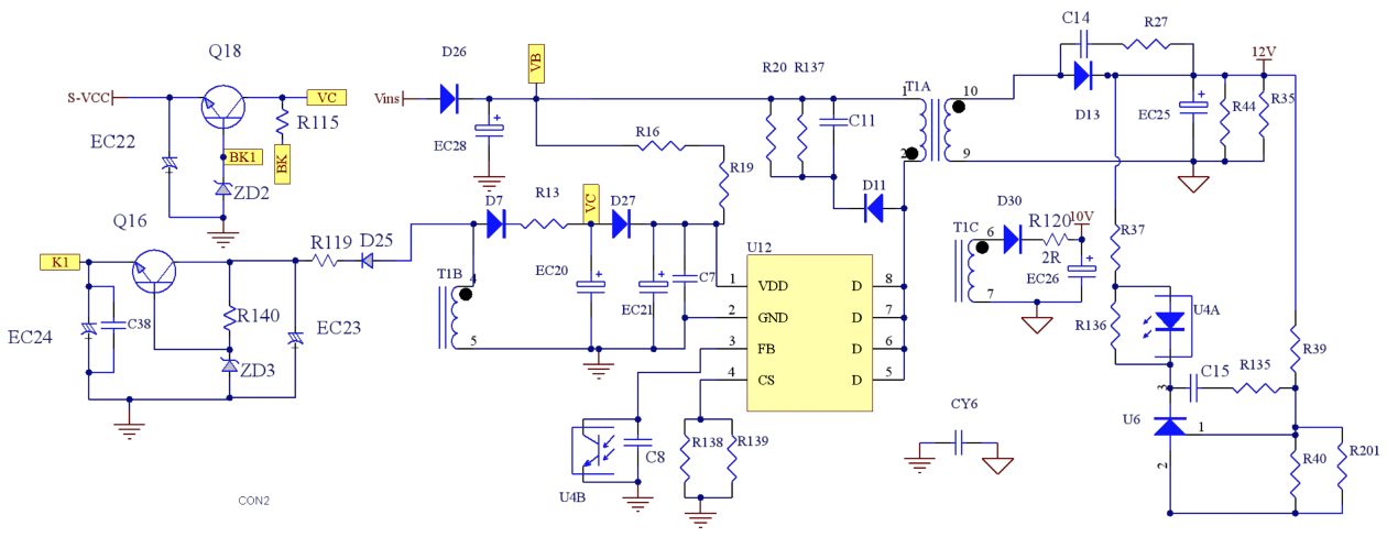
Circuit diagram:
Key components BOM list:
| Component | Specification |
|---|---|
| Input E-CAP | 18µF / 400V (sized at ≥ 1.5µF/W) |
| Power transformer | EE1610, Lp = 1000µH |
| Rectifier diode | SS310, 3A / 100V (Schottky) |
| Output E-CAP | 470µF / 25V |
| Flyback controller IC | CR5269S (QR mode, built-in MOSFET) |
Circuit efficiency and main heat-generating devices:
This circuit's efficiency is 85%; total heat is below 2W, distributed among the transformer, controller IC and rectifier.