Isolated DC-DC scheme for input voltage below 40V and output power below 5W
For small isolated DC-DC solutions up to 15W, the first choice is a single-chip flyback power IC integrating the switch and controller — switch, controller, driver, regulated feedback and protection all on one chip: simple, reliable, high operating frequency, small size. Foreign vendors include Analog Devices (Linear) and MPS; domestic vendors include Joulwatt and Xianyike.
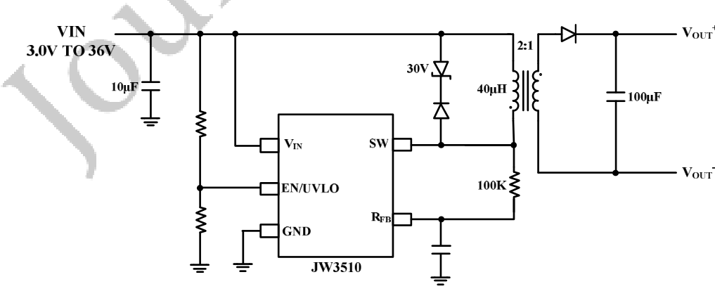
For up to 5W, the cost-effective JW3510 scheme is recommended first:
Chip model: JW3510, volume reference price RMB 2
Input voltage: 4.5V ~ 40V
- Output voltage
- > 2.5V (different output voltages require adjusting the transformer winding turns)
- Output power
- <= 5W
- Input current limit
- 1.4A
- Input MOSFET voltage rating
- 65V
- Transformer calculation
- see Flyback AC-DC Power Supply Design; an EE10 transformer is sufficient
- Input/output capacitors
- ceramic, or high-frequency low-ESR electrolytic
- Operating frequency
- up to 430kHz
- Chip package
- SOT23-5
- Typical efficiency
- 80% (12V input, 5V 0.8A output)
Features: ultra-small size, heavy-load QR mode, built-in MOSFET, multiple protections, no optocoupler or winding regulation needed
Design case: 5V/0.5A isolated DC-DC module
Applications: consumer electronics, communications, industrial control, isolated communication supply for high-power systems
Typical application circuit:
Isolated DC-DC scheme for input below 40V and output power 5~15W
For small isolated DC-DC solutions up to 15W, the first choice is a single-chip flyback power IC integrating the switch and controller — switch, controller, driver, regulated feedback and protection all on one chip: simple, reliable, high operating frequency, small size. Foreign vendors include Analog Devices (Linear) and MPS; domestic vendors include Joulwatt and Xianyike.
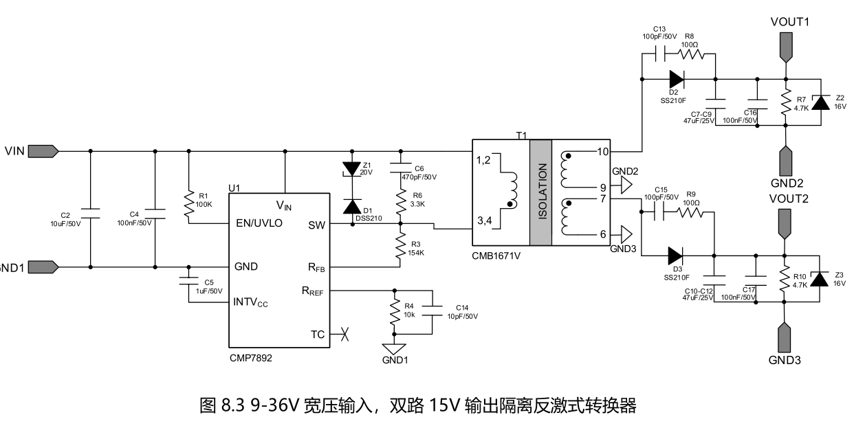
For the 5~15W range, the CMP7892 from Xianyike is recommended:
Chip model: CMP7892, volume reference price RMB 5
Input voltage: 4.5V ~ 45V
- Output voltage
- > 2.5V (different output voltages require adjusting the transformer winding turns)
- Output power
- <= 15W
- Input current limit
- 3.6A
- Input MOSFET voltage rating
- 70V
- Transformer calculation
- see Flyback AC-DC Power Supply Design; an EE13 transformer suffices
- Input/output capacitors
- ceramic, or high-frequency low-ESR electrolytic
- Operating frequency
- up to 380kHz
- Chip package
- ESOP-8l
- Typical efficiency
- 80% (12V input, 5V 2A output)
- Features
- 3 operating modes BCM/DCM/Burst, built-in MOSFET, multiple protections, no optocoupler or winding regulation needed
- Design case
- dual 15V/0.5A isolated DC-DC module
Applications: consumer electronics, communications, industrial control, isolated communication supply for high-power systems
Typical application circuit:
Isolated DC-DC scheme for input above 20V and output power 15W~50W
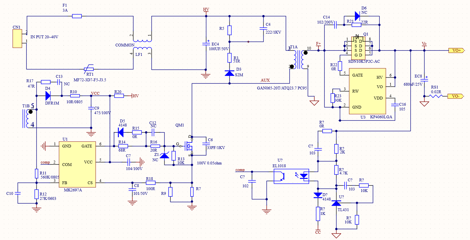
For this class of isolated DC-DC, the following "QR flyback controller + external MOSFET" flyback scheme is recommended:
Main controller: MK2697
Input voltage: above 20V (MK2697 VCC operating range 9V ~ 90V)
- Output voltage
- > 2.5V (different power and output voltages require adjusting transformer parameters)
- Output power
- 10~50W
- Input current limit
- 6A
- Primary MOSFET
- 100V 50mΩ
- Secondary MOSFET
- synchronous rectification, 40V 5mΩ
- Transformer calculation
- see Flyback AC-DC Power Supply Design; EE13~EE16 transformer (depending on power)
- Input/output capacitors
- high-frequency low-ESR electrolytic
- Operating frequency
- up to 200kHz
- Chip package
- SOT-26
- Typical efficiency
- 85% (24V input, 12V 2A output)
Features: 3 operating modes QR/DCM/Burst, strong MOSFET drive capability, multiple protections
Design case: dual 15V/0.5A isolated DC-DC module
Applications: consumer electronics, industrial control
Typical application circuit:
Isolated DC-DC scheme for input below 40V and output power below 500W (medium-high power)
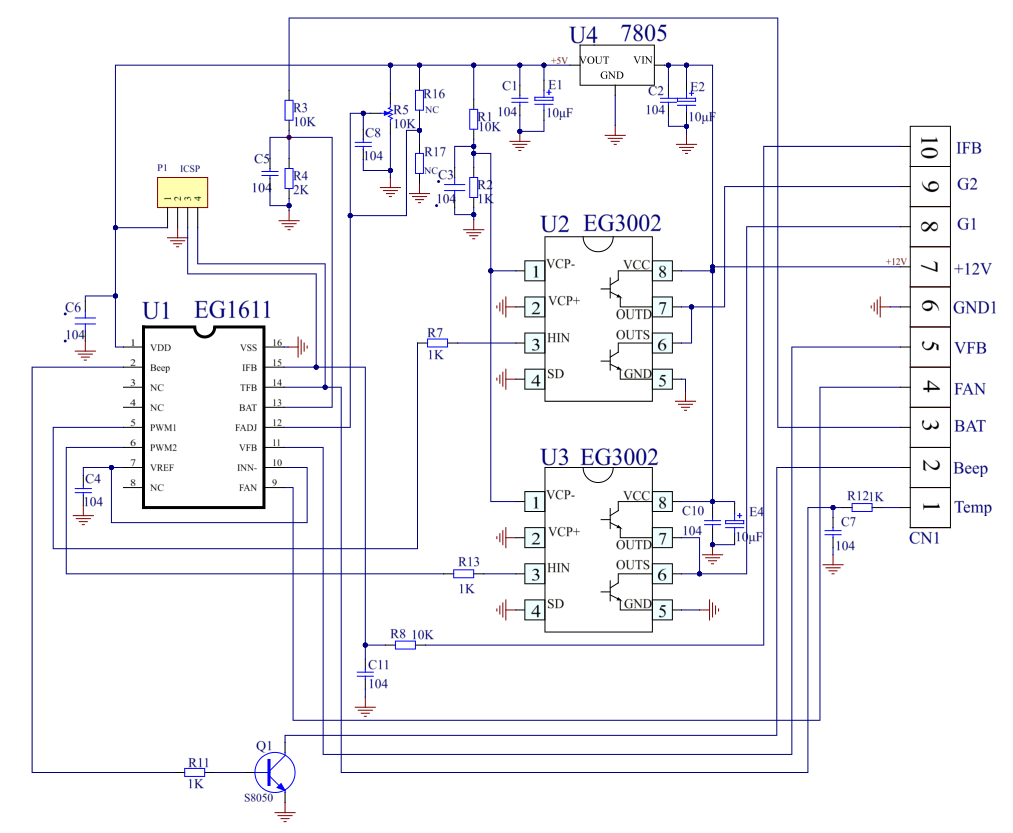
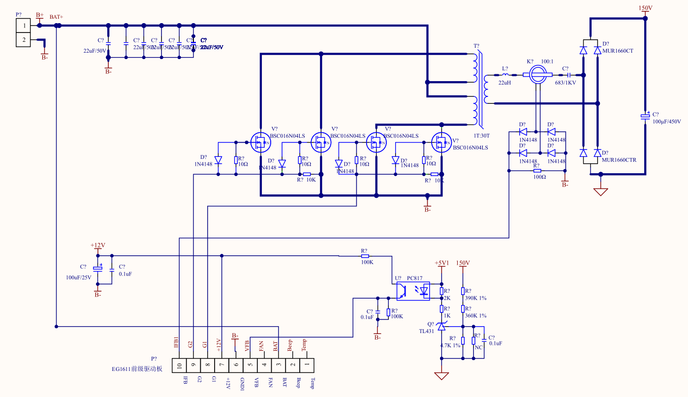
For medium-high power with input below 40V, a push-pull scheme is generally used; above 500W, use the full-bridge scheme in Section 5 below. EG Micro's push-pull scheme:
- Main controller
- EG1611
- Push-pull driver chip
- EG3002
Input voltage: 10~40V
- Output power
- max 500W
- Primary MOSFET
- Vds>2.4*Vin; Rds(on) and switching speed as small as possible
- Secondary rectifier
- voltage rating >1.5Vout, fast-recovery diode; for output below 40V a center-tapped configuration can be used instead.
Transformer & inductor calculation: see Push-Pull & Full-Bridge Transformer Output Inductor Calculation; 500W push-pull uses PQ3530
- Input/output capacitors
- high-frequency low-ESR electrolytic
- Operating frequency
- 40~120kHz
- Chip package
- SOP16
- Typical efficiency
- 88% (12V input, 150V 3A output)
- Features
- under-closed-loop output voltage feedback, soft start, 50% duty-cycle output, 500ns dead time
Voltage, current and temperature feedback processed in real time; over-voltage, under-voltage, over-current and over-temperature protection
Design case: 12V lead-acid battery input, 120V DC output
Applications: energy-storage conversion, inverter front stage, outdoor power supply, industrial control
Circuit example:
High-power isolated DC-DC scheme for above 500W or high input voltage:
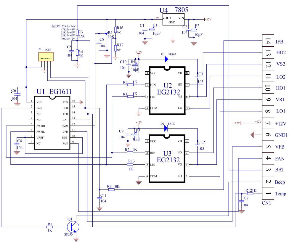
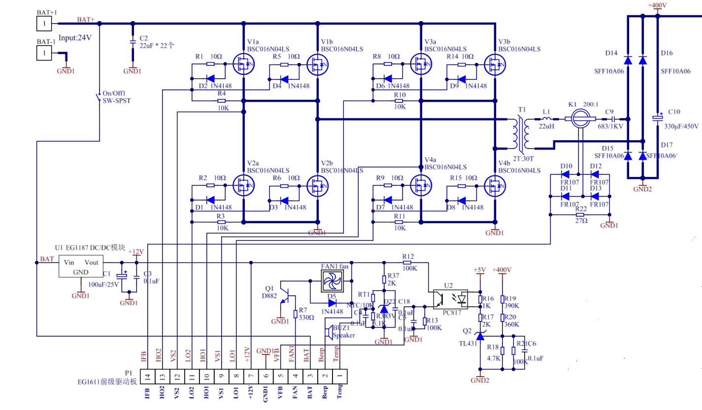
High-power DC-DC designs generally use full-bridge or quasi-resonant full-bridge topologies to raise efficiency and reduce size. EG Micro's quasi-resonant full-bridge scheme:
- Main controller
- EG1611 (this chip can also be configured for full-bridge mode)
- Full-bridge driver chip
- EG2132
Input voltage: >10V
- Output power
- >500W
- Primary MOSFET
- Vds>1.2*Vin; Rds(on) and switching speed as small as possible
- Secondary rectifier
- voltage rating >1.5Vout, fast-recovery diode; for output below 40V a center-tapped configuration can be used instead.
- Operating frequency
- 40~120kHz
- Chip package
- SOP16
- Typical efficiency
- 89% (24V input, 400V 3A output)
- Features
- under-closed-loop output voltage feedback, soft start, 50% duty-cycle output, 500ns dead time
Voltage, current and temperature feedback processed in real time; over-voltage, under-voltage, over-current and over-temperature protection
- Design case
- 24V battery input, 400V DC output
- Transformer calculation
- see Push-Pull & Full-Bridge Transformer Output Inductor Calculation; 1000W full-bridge uses PQ4030
- Input/output capacitors
- high-frequency low-ESR electrolytic
Applications: energy-storage conversion, inverter front stage, outdoor power supply, industrial control
Circuit example: